
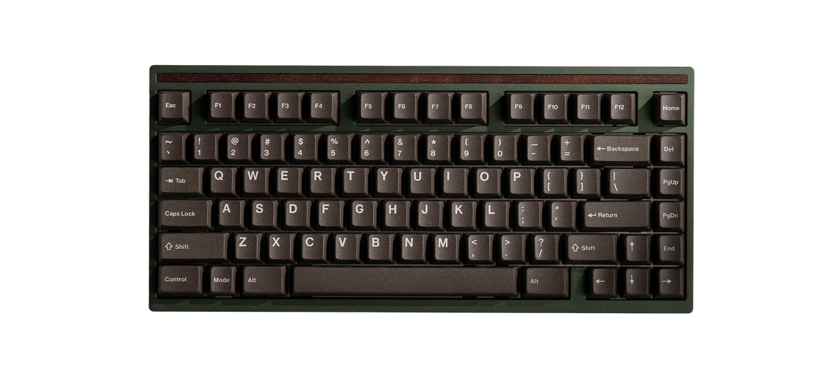
Encore Build Guide
Build Time: 45-90 minutesParts
- Case
- PCB
- Plate
- Daughterboard
- Wavespring Bolts (for the Crown Mounting System) x8
- Screwdriver
- Silicone Feet
- Fastener Pack
- Keycap & Switch Puller
- Optional Standoff Fasteners
Preparation
Check that you have the required parts and tools listed above. We recommend the following steps to get the most out of your Encore.
Lubing Stabilizers: This reduces the rattling sounds that stock stabilizers produce. We have our own video tutorial available here.
The Crown Mounting System
The 2026 Encore is built around our new Crown Mounting System. It creates a lively and comfortable typing experience through a wavespring, silicone spool, and bushing stacked on a custom shoulder bolt. It's designed for top-mount stability while keeping the typing feel responsive. Click here to learn more about the making of the Crown Mounting System.
Fasteners

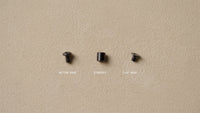
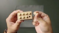
There are up to 5 types of fasteners used in this keyboard. The wood and case fasteners will be pre-installed onto the keyboard chassis. This diagram can be referenced to confirm that you are using the correct ones.
The optional standoff fasteners will come in a separate bag containing the button head fasteners, flat head fasteners, and the standoffs themselves.

Step 1: Test PCB
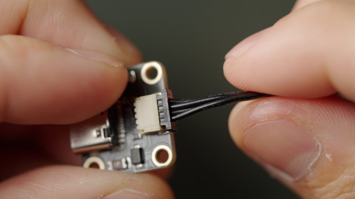


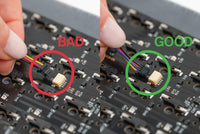
Do not skip this step; we cannot guarantee a replacement PCB that was not tested prior to assembly.
-
- Open VIA, navigate to the Key Tester tab, and enable Test Matrix mode. This process will still work, even if the Test Matrix mode is not functioning.
-
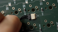
- Place the PCB facedown, connect the daughterboard to the PCB, and plug it in.
Ensure the cable is going in straight, with the pins on the cable facing downwards.
-
- Touch the ends of your tweezers to the metal contacts under each switch position, lighting up each key in VIA. Note that the function key may not light up.
-
- In the rare event that keys do not light up, pause your build here and contact support@modedesigns.com.
Step 2: Install PE foam sheet (optional)
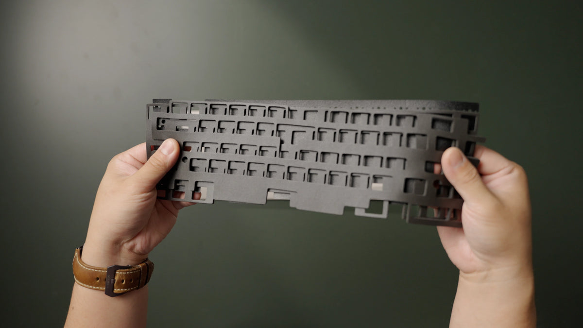

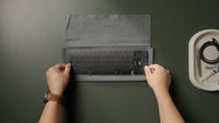
-
- If you plan to use the optional PE foam, lay it on top of the PCB now (foam kit sold separately).
Step 3: Install Stabilizers
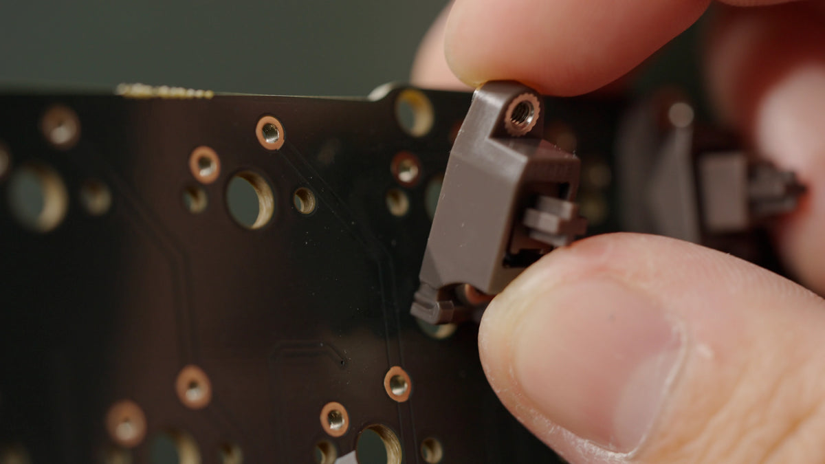


Stabilizers ensure that long keys actuate properly, no matter where you press. The stabilizer wire you need for the spacebar will depend on your choice of layout.
-
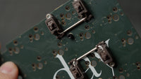
- Insert the non-threaded end of the stabilizer into the larger cutout on the PCB, then pivot the threaded ends into place.
-
- Ensure that your stabilizers are completely flat on the PCB before screwing them in.
-
- While bracing the front of each stabilizer, screw it into place from the underside of the PCB. Repeat for the remaining stabilizers.
-
- You can watch our in-depth stabilizer lubing and tuning tutorial here.
Step 4: Install standoffs (optional), plate foam, and plate


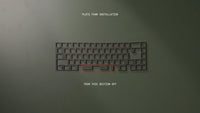
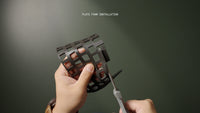
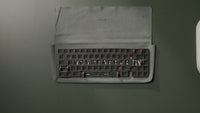
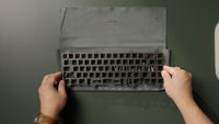
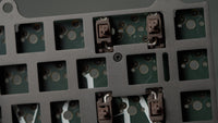
Your keyboard plate holds the switches in place on the PCB, and its material can influence the board's sound and feel. Generally, stiffer materials result in a brighter, clackier sound profile, while softer materials are deeper and quieter sounding.
-
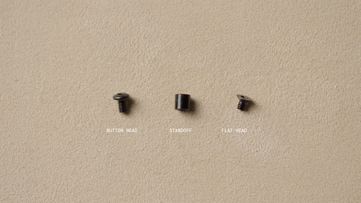
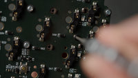
- Your kit includes optional standoff screws that act as a rigid spacer between the PCB and plate. These can make installation a little easier but may also alter the sound profile of the board. To use them, put one of the button head screws through the back of the PCB in a standoff hole, screw a standoff onto it on the front side, and repeat for all standoff holes.
-
- If you plan to use the optional plate foam for a more dampened sound, you will need to trim the spacebar section using scissors. Once trimmed, you can lay it on top of the PCB in the orientation shown here.
-
- Top the PCB with your plate of choice. If you installed the standoffs, use the countersunk screws to secure the plate to the PCB. If you did not use the standoffs or plate foam, the plate will not be secured until you install some switches.
Step 5: Install Switches


-
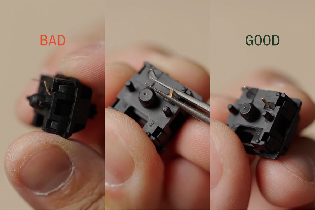
- Before installing your switches, inspect them to ensure the two metal pins on the underside of each switch are straight. Straighten all pins with tweezers if any are bent.
-
- Insert switches into the plate/PCB. Take care to brace the back of the hotswap socket with a finger while pushing the switches into place with your thumb. Do not apply downward pressure to the surface of the plate itself.
-
- Install your first few switches around the plate as shown, this will help ensure the plate stays aligned during the installation process.
-
- Install remaining switches, working your way in from the corner switches.
If you have a solder PCB, solder your switches now.
Step 6: Notice for Softer Plates
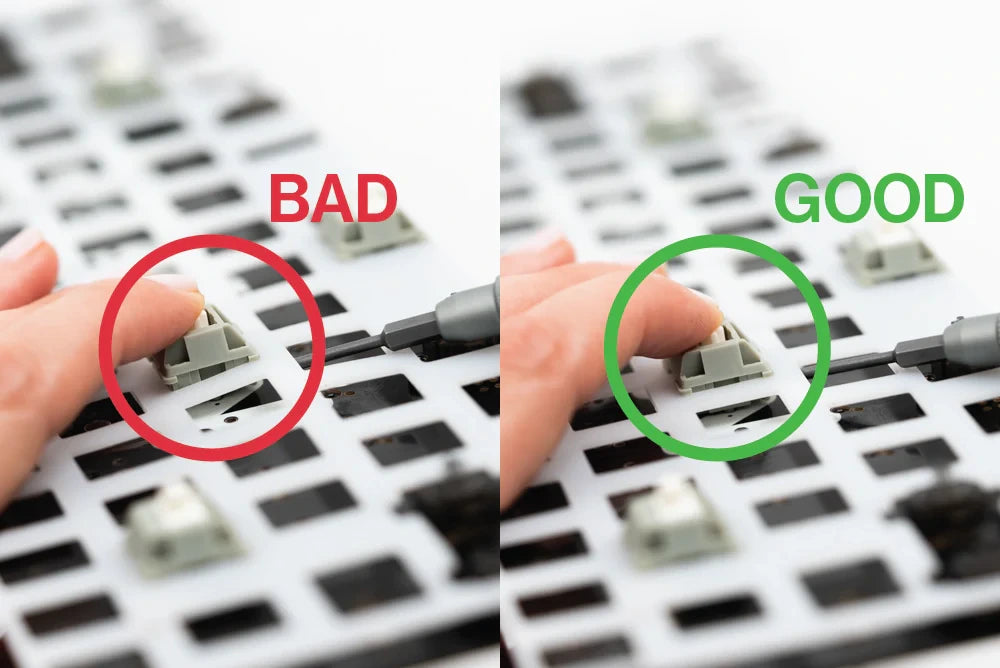

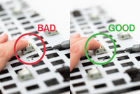
If you are using a softer plate material such as Nylon, PP, Pom, or PC, ensure switches are fully seated. We recommend using the screwdriver to carefully lift the plate while pressing down on the switch to ensure the switch is seated flat on the plate.
Step 7: Check Switch Installation
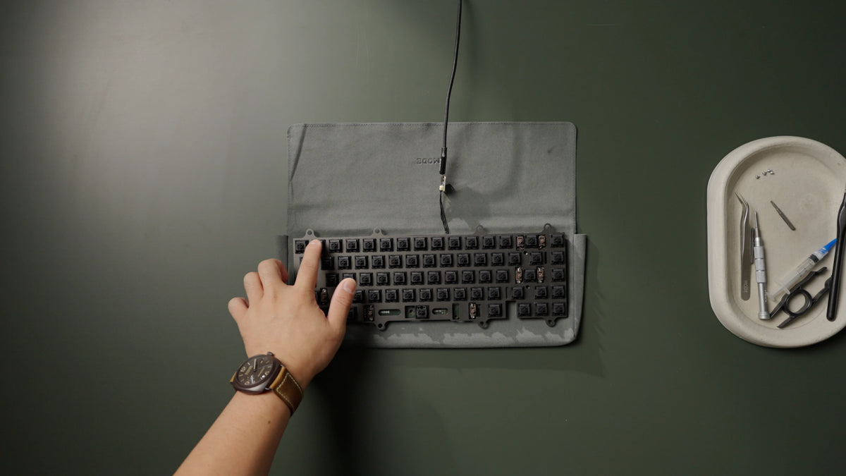

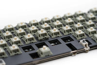
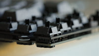
Switches that are not properly installed can cause alignment issues when the case is closed.
-
- Check that the plate is not sagging below the tops of the switches.
-
- Check that each switch pin is fully seated into the PCB. You may hear an audible snap every time a switch is properly inserted into the plate.
-
- We also recommend reconnecting the daughterboard and testing the PCB again in VIA to make sure everything is working properly. If a key is not triggering, a pin is most likely bent and needs to be reinstalled.
-
Once everything works, your internal assembly is complete. Set it aside and grab your keyboard chassis next.
Step 8: Disassembly
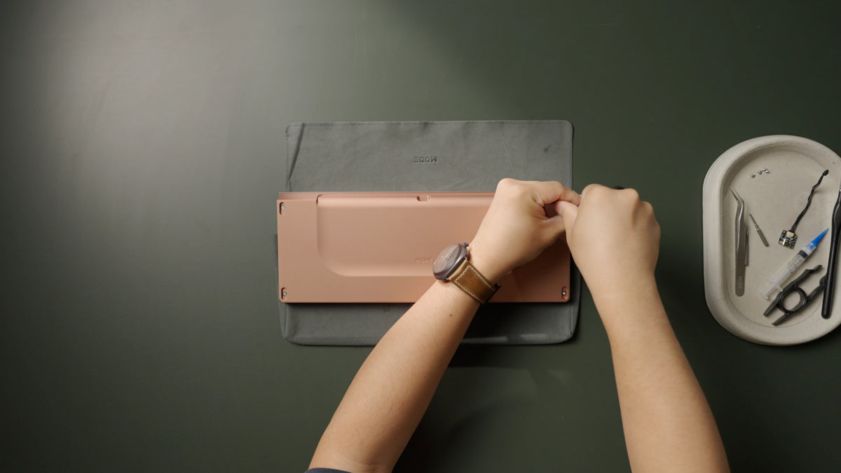

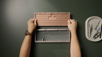
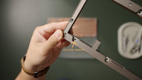
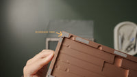
-
- The Encore ships with the top case and bottom case pre-assembled.
-
- Place your keyboard face down on a soft surface. From the bottom of the board, use the H2.0 bit to remove the case fasteners (four total), and place those screws to the side.
-
- Flip the top case over and check for two things. Within the top case, you should find silicone rings pre-installed around each mounting thread. In the bottom case, you should find microsuede pads around the perimeter. These help shape the acoustics of the keyboard.
-
- If any of these components are missing, pause your build and contact support@modedesigns.com.
Step 9: Install the Crown Mounting System
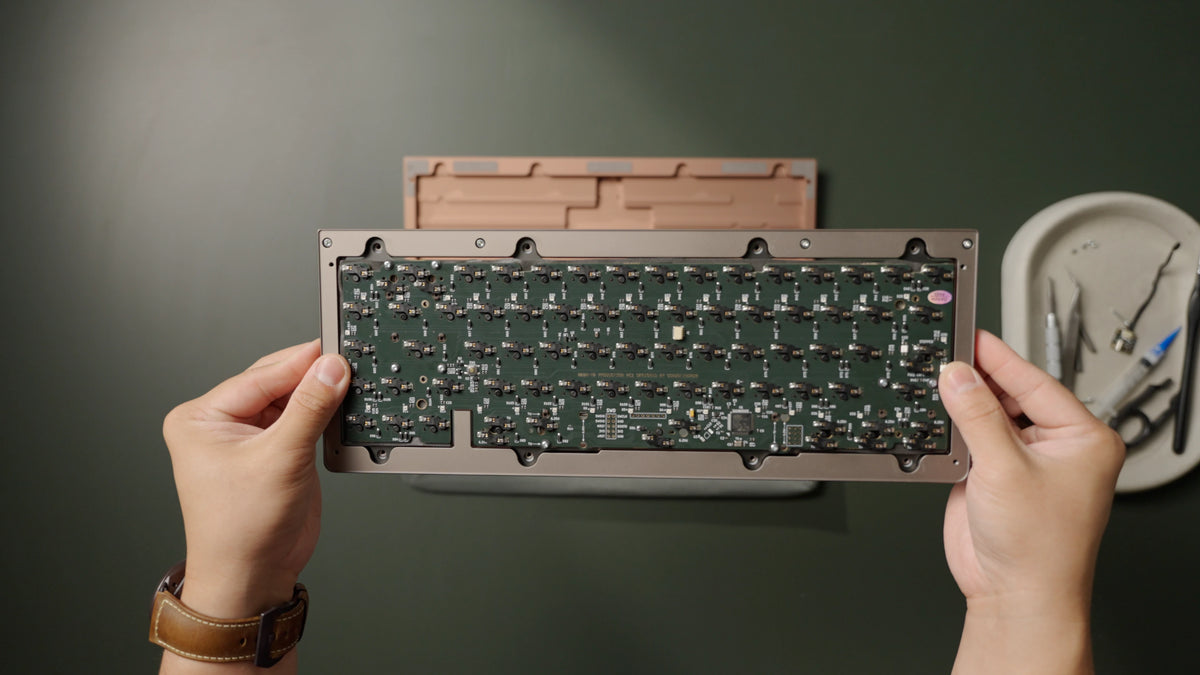


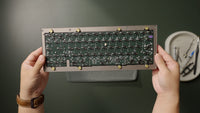
Next, install the internal assembly into the top case. In your board's packaging, you can use the cardboard tray as a work surface so the top case sits flat during installation.
-
- Place the internal assembly face down into the top case. This can only go in one way, with the cutout on the PCB matching the blocker on the top case.
-
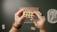
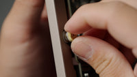
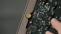
- In your accessories tray, find the small box containing the pre-assembled wavespring bolts. These consist of the shoulder bolt, a silicone ring, the wavespring within a silicone spool, and a bushing. They are designed to come apart, so ensure each stack is assembled in this order.
-
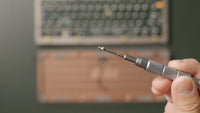
- Keeping each stack together, flip it over and screw it into each mounting point, just until it stops. We recommend finger-tightening these, but you can also carefully use the H1.5 bit.
The shoulder bolts are designed to come to a complete stop, so as soon as one stops fully, do not attempt to tighten further.
-
- If you purchased the optional top-mount bolts, install them the same way. They provide a more rigid typing experience while removing some of the harshness that typically comes with a top-mount assembly.
-
Once that's complete, set your top case aside and grab your bottom case, daughterboard and cable, and optional case foam.
Step 10: Install Daughterboard


-
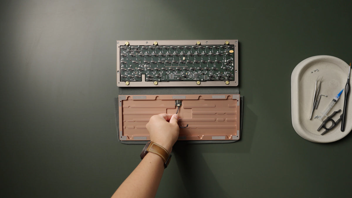
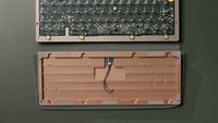
- Ensure the daughterboard cable is connected securely to the daughterboard, taking care not to bend the pins in the connector.
-
- Hold the daughterboard by the cable with the cutout facing down to align it to the bottom case, then fasten it into the bottom case using the M2x3 fasteners (four total).
Take care to not overtighten the fasteners, or you may damage the daughterboard.
Step 11: Install Case Foam (optional)
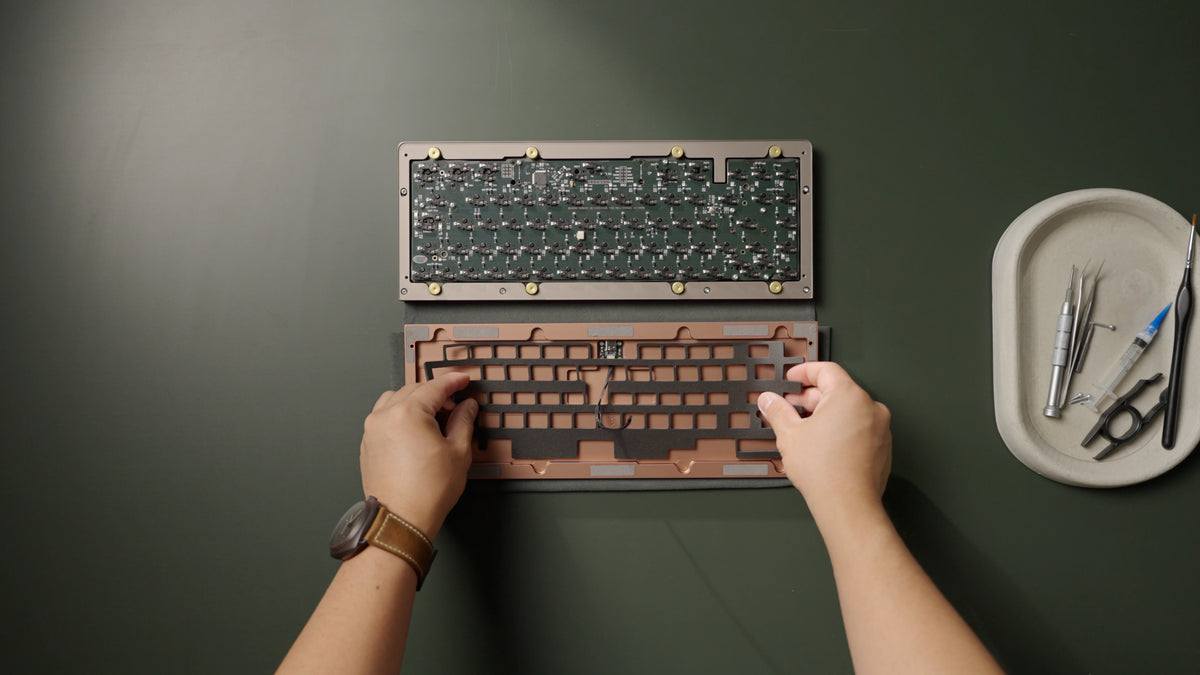


-
- If you plan to use the optional case foam for a more dampened sound, lay it on the back of your PCB now, in this orientation, threading the JST cable through the center cutout.
Step 12: Secure Top and Bottom Case, Install Feet
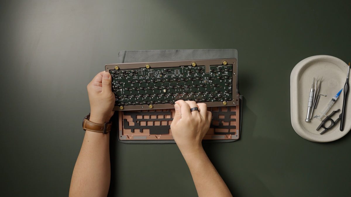


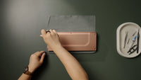

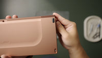
-
- While holding the top case upside down, attach the daughterboard cable to the PCB. Lay the top case flat onto the bottom case. The bottom case should rest within the small lip that goes around the edge of the top case.
Ensure the pins on the cable are facing downward and the cable goes in perfectly straight.
-
- Carefully flip the board over, fasten the bottom case to the top case with the M2.5x14 fasteners along the top of the board (two total) and the M2.5x6 fasteners along the bottom of the board (two total).
-
- Install the rear feet by aligning each foot with its recess and pushing it in with the flat side facing inward. All four silicone feet are exactly the same. Ensure the pointed side is facing outwards.
Step 13: Install Keycaps and Tune Stabilizers
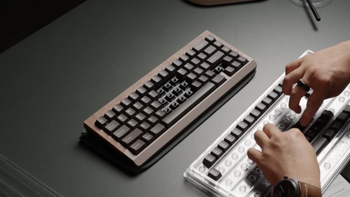


-
- Install your MX-compatible keycaps.
-
- Test the stabilized keys for any undesired rattling noises.
-
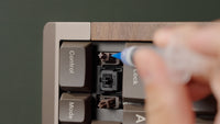
- If rattle is detected, remove the keycap, lift the corresponding stem up and inject lube into the slider around the ends of the stabilizer wires.
Step 14: Set macOS layout
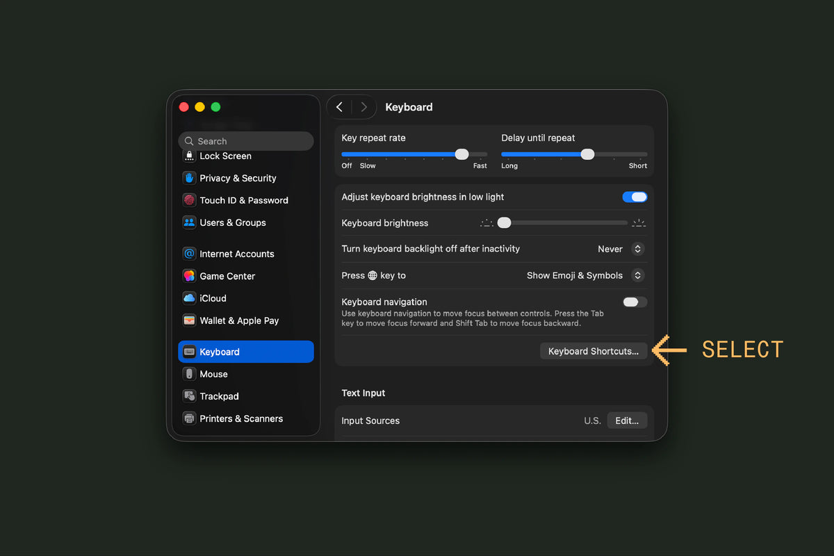

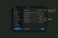
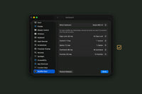
If you are using your Encore with a Mac, switch the Command and Option key positions in System Preferences. You will only need to do this one time, and the positions will be correct for both Mac and PC usage.
-
- Under the keyboard settings in System Preferences, select Keyboard Shortcuts.
-
- Select your keyboard at the top. This will match the PCB name that comes up in VIA.
Step 15: Program Keymap in VIA/QMK

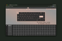
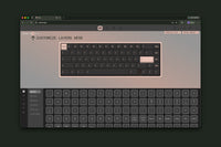
The Encore is fully compatible with VIA and QMK. You can use the graphical interface of VIA to program any of the keys or layers on the Encore. By default, the key to the right of the spacebar is programmed to MO(1). Hold this key down and press the matching key in the number row to reach F1 through F12.
-
- If using QMK, you may enter bootloader mode by pressing the physical reset button on the board or pressing Fn + Esc.
-
- If any of the keys do not actuate properly, it may be due to a bent switch pin during installation. Remove that keycap and switch using a keycap/switch puller. If any metal pins are bent, straighten them with a pair of tweezers.
-
- For more information on how to use VIA, you can view their documentation here.
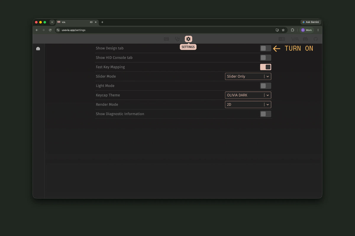
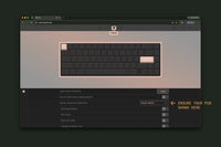
If you are using the 2026 PCB or newer, VIA may not recognize your board automatically. Save the M65 V2 definition file to your computer (right-click and choose Save Link As), then load it in VIA under the Design tab. The Design tab is hidden by default; turn it on in VIA's Settings.
Happy Typing
We hope you had a smooth build experience and would love to see the end result! Post your build in our photos channels on Discord or tag us on Instagram @modekeyboards. If you have any feedback you'd like to share with us, you can reach out to hi@modedesigns.com.
FAQ
-
It's mostly an aesthetic choice, and it comes down to how the bottom row is sized. A 6.25U spacebar leaves room for one extra switch, with each of the surrounding bottom-row keycaps measuring 1.25U. A 7U spacebar is wider and uses a 1.5U, 1U, 1.5U, and 1.5U arrangement around it, with one fewer switch than the 6.25U layout. Both are supported, and you can switch between them in VIA under the Layout tab.
-
This one comes down to preference and your keycap set. A standard caps lock is a flat 1.75U key. A stepped caps lock uses the same 1.75U footprint but adds a raised step, so the pressable surface is 1.25U with a ledge beside it, a nod to classic layouts. Both are supported. Just make sure your keycap set includes the style you want, and place the switch in the position shown on the back of the PCB silkscreen for your chosen layout.
-
The Encore is a 65% layout, so it doesn't have a dedicated F-row. Those keys live on a secondary layer. Hold the Fn key and press the matching key in the number row to reach F1 through F12. You can view and remap everything on each layer in VIA under the Configure tab. In VIA, you can also assign many of the macOS F-row functions to your keys, like volume, playback, and brightness controls. A few macOS-specific functions won't map over, which is common with the majority of custom keyboards.
-
Sluggish or sticking return on the long keys almost always traces back to the stabilizers. Pull the keycap and check that the stabilizer sits flat on the PCB and that the wire is fully seated in both the housing and the stem. If the wire has popped loose or sits at an angle, reseat it. An over-lubed stabilizer can also feel sluggish, in which case you'll want to clean out the excess lube with a q-tip or a dry brush. Finally, make sure the keycap is pressed evenly onto both the switch stem and the stabilizer stems, since an uneven keycap can catch.
-
Ticking usually means the stabilizer wire needs a little lube. Pull the keycap, lift the stem, and inject a small amount of lube into the housing around the ends of the stabilizer wire, a little at a time so you don't overdo it. Reseat the keycap and test again. You can follow our full stabilizer tutorial here.
-
The Encore works with any MX-compatible switches and keycaps, whether you get them from us or elsewhere. For a 65% layout, just make sure your keycap set covers the bottom-row sizes for the layout you're building, including your choice of spacebar and any stepped or split keys. A set of 70 switches is perfect to cover the layout with a few spares.
-
No, the Encore is a wired keyboard that connects over USB-C.
-
Yes, the Encore works with both. If you're on a Mac, switch the Command and Option key positions once in System Preferences, as covered in the macOS layout step above, and you'll be set for both Mac and PC use.
-
The foam kit is optional and used to fine-tune your board's acoustics for a deeper, more muted sound. It has three layers, each doing a different job. PE foam softens the sharp clack of bottoming out, plate foam fills the space between the PCB and plate to cut reverb, and case foam adds a final layer of dampening toward the bottom case. You can use any combination of the three, or none at all.
-
It comes down to the sound and feel you're after. As a general rule, stiffer materials give a brighter, clackier sound and a firmer typing feel, while softer materials are deeper and quieter with more flex. There's no wrong answer here, so it's worth trying a few over time to find what you like.
-
While the Wavespring Bolts are optimized for a balanced, responsive yet comfortable typing feel, you can opt for a firmer typing experience with the optional top-mount bolts (sold separately).
-
We recommend lubing your stabilizers, since it makes a noticeable difference in cutting rattle. Switches are optional. Most switches these days sound and feel good stock, so additional lubing isn't required unless you want to fine-tune them further.
-
Yes. The Encore is designed to come apart, so you can swap between the wavespring and top-mount bolts, add or remove foam, or change your plate whenever you like. Just reverse the relevant assembly steps to get back inside.
-
If you run into an issue that isn't covered here, or you're not sure how to proceed, reach out to our support team at support@modedesigns.com and we'll help you get it sorted.